


John Deere 2100 Minimum Till Ripper
Vertical Tillage
Your Preferred Location
Specifications
Closing wheel attachment - Angle adjustments: |
0 to 15 degree (angle) |
Closing wheel attachment - Description: |
Two adjustable wheels on 3-, 4-, 5- and 7-standard sizes. Four adjustable wheels on 9-standard integral only. Drawn hitch machines do not require stabilizer wheels. |
Closing wheel attachment - Down force: |
113.4 kg 250 lb |
Closing wheel attachment - Size: |
10.2x40.6 cm 4x16 in. |
Closing wheel attachment - Spacing: |
19.05 to 35.6 cm 7.5 to 14 in. |
Coulters - Blades: |
Straight or rippled: 559x4.5 mm 22x0.177 in. |
Coulters - Pounds of force: |
Normal working load: 272.2 kg 600 lb Deflection of: 10.2 cm 4 in. Maximum trip load: 362.9 kg 800 lb Deflection of: 20.3 cm 8 in. |
Coulters - Type: |
Spring cushion coulters |
Depth control - Option 1: |
3-point hitch for integral |
Depth control - Option 2: |
Single point for pull-type |
Frame - Maximum underframe clearance: |
89 cm 35 in. |
Frame - Size: |
102x152x0.9.5 mm 4x6x0.375 in. 9 standard: 152x152x9.5 mm 6x6x0.35 in. |
Ground-engaging components - Options: |
Standard: 19 mm (0.75 in.), min-till point: 178 mm (7 in.), low-disturbance: 254 mm (10 in.), ultra-low-disturbance: 63 mm (2.5 in.) Standard: 31.75 mm (1.25 in.), Regular: 57 mm (2.25 in.), Capped: 57 mm (2.25 in.), Double-capped: 57 mm (2.25 in.) LaserRip points: 70 mm (2.75 in.), 127 mm (5 in.), and 178 mm (7 in.) |
Hitch - Options: |
Integral, or 7- or 9-standard pull type |
Hitch - Pull-type description: |
Level Lift |
Hitch - Three-point hitch requirements: |
Category 2, Category 3 and 3N (with Quik-Coupler) |
Horsepower required - Horsepower per standard: |
22.3-29.8 kW 30-40 hp Depending on soil type, moisture, and depth of operation NOTE: Maximum compatible tractor engine - 231.2 kW 310 hp |
Hydraulic requirements - Option 1: |
Pull type: 1 SCV (lift) at 17,237 kPa 2500 psi for optimum raise times |
Hydraulic requirements - Option 2: |
Low transport: 1 SCV (fold) at 17,237 kPa 2,500 psi for optimum raise times |
Key Specs - Horsepower per standard: |
22.3-29.8 kW 30-40 hp Depending on soil type, moisture, and depth of operation NOTE: Maximum compatible tractor engine - 231.2 kW 310 hp |
Key Specs - Miles per hour: |
6.4-8 km/h 4-5 mph |
Key Specs - Operating depth: |
Maximum 40.6 cm 16 in. |
Key Specs - Spacings: |
76.2 cm 30 in. 91.4 cm 36 in. |
Key Specs - Transport width: |
3.05 m 10 ft 4.1 m 13.5 ft 5 m 16.5 ft 6.7 m 22 ft 4.7 m 15.5 ft |
Key Specs - Working width: |
2.3 m 7.5 ft 2.7 m 9 ft 3.05 m 10 ft 3.8 m 12.5 ft 4.6 m 15 ft 5.3 m 17.5 ft 6.8 m 22.5 ft |
Operating depth - Maximum: |
40.6 cm 16 in. |
Operating speed - Miles per hour: |
6.4-8 km/h 4-5 mph |
Pull-type wheels - Additional feature: |
Replaceable wear shin |
Pull-type wheels - Description: |
12.5L-15 tires for 9-standard pull-type; 11L-15 tires for 7-standard, pull-type; 9-standard has 8-bolt hubs and spindles |
Pull-type wheels - Option 1: |
Set back brackets |
Stabilizer/gauge wheels - Tires: |
10 PR |
Stabilizer/gauge wheels - Type: |
Stabilizer wheels |
Stabilizer/gauge wheels - Wheels: |
52.1x20.3 cm 20.5x8 in. |
Standard options - Option 1: |
Trip force Shear bolt: 3,265.9 kg 7,200 lb Standard type 19 mm 0.75 in. or 31.75 mm 1.25 in. Straight with wear shin Shear-bolt |
Standard options - Option 2: |
Trip force 1,451.5 kg 3,200 lb Trip height 30.5 cm 12 in. Standard type 19 mm 0.75 in. Cushion trip |
Standard options - Option 3: |
|
Standard options - Option 4: |
|
Standard options - Spacings: |
76.2 cm 30 in. 91.4 cm 36 in. |
Tool configuration - Option 1: |
Standard: 3, spacing: 76.2 cm 30 in. |
Tool configuration - Option 2: |
Standard: 3, spacing: 91.4 cm 36 in. |
Tool configuration - Option 3: |
Standard: 4, spacing: 76.2 cm 30 in. |
Tool configuration - Option 4: |
Standard: 5, spacing: 76.2 cm 30 in. |
Tool configuration - Option 5: |
Standard: 5, spacing: 91.4 cm 36 in. |
Tool configuration - Option 6: |
Standard: 7, spacing: 76.2 cm 30 in. |
Tool configuration - Option 7: |
Standard: 9, spacing: 76.2 cm 30 in. Rigid |
Tool configuration - Option 8: |
Standard: 9, spacing: 76.2 cm 30 in. Folding |
Tool configuration - Type: |
In-line ripper |
Transport width - Option 1: |
3.05 m 10 ft |
Transport width - Option 2: |
3.05 m 10 ft |
Transport width - Option 3: |
3.05 m 10 ft |
Transport width - Option 4: |
4.1 m 13.5 ft |
Transport width - Option 5: |
4.1 m 13.5 ft |
Transport width - Option 6: |
5 m 16.5 ft |
Transport width - Option 7: |
6.7 m 22 ft |
Transport width - Option 8: |
4.7 m 15.5 ft |
Working width - Option 1: |
2.3 m 7.5 ft |
Working width - Option 2: |
2.7 m 9 ft |
Working width - Option 3: |
3.05 m 10 ft |
Working width - Option 4: |
3.8 m 12.5 ft |
Working width - Option 5: |
4.6 m 15 ft |
Working width - Option 6: |
5.3 m 17.5 ft |
Working width - Option 7: |
6.8 m 22.5 ft |
Working width - Option 8: |
6.8 m 22.5 ft |
Heavy-duty frame handles tough operating conditions
 Frame on seven-standard model
The frame is constructed with a 102-mm x 152-mm x 10-mm (4-in. x 6-in. x 0.375-in.) cross tube on three-, four-, five-, and seven-standard machines and 152-mm x 152-mm x 10-mm (6-in. x 6-in. x 0.375-in.) cross tube on nine-standard models where the hitch-mounting components are welded for maximum strength.
Truss tubes connect the cross tubes and are constructed with 127-mm x 127-mm x 13-mm (5-in. x 5-in. x 0.5-in.) steel tubing.
Welded together into one assembly, the frame is designed to handle the most severe operating conditions.
The mainframe is 4.06-m (160-in.) wide and is the same whether there are five shanks on 762-mm (30-in.) spacings. Frame extensions make this task possible and make configurations easier to adjust.
Spring-cushion coulters enable more level soil profile
 Straight blade shown
Cushion coulters cut and size residue and pre-slice the soil to allow a more level soil profile:
- 559-mm x 5-mm (22-in. x 0.177-in.) straight blade is in base equipment and allows the least amount of soil and residue disturbance.
- 559-mm x 5-mm (22-in. x 0.177-in.) rippled blade is optional equipment for use when increased soil movement is desired.
Closing wheel available to minimize surface disturbance
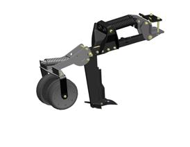 Closing wheel
Closing wheels can be added to the rear of the 2100 Minimum-Till Ripper with 19-mm (0.75-in.) standards.
Closing wheels offer the following benefits:
- Minimize surface disturbance created by the standard
- Provide more adjustments to match farming practices and varying soil conditions than competitive models
- 114 kg (250 lb) of down pressure
- Mounted close to the shank, allowing a high trip clearance for operation through washouts, etc.
- Mounted with an L-bracket, allowing better soil and residue flow
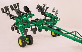
2100 Drawn Hitch option available for seven- and nine-standard models
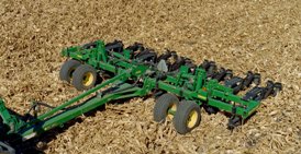 Nine-standard drawn hitch
A drawn hitch option is available for those who want to use large row-crop tractors or 4WD tractors without a 3-point hitch.
The drawn hitch is only compatible with seven-standard and nine-standard 762-mm (30-in.) models. The drawn hitch is also available as an attachment for field conversion.
The transport wheels are placed in front of the front rank of the mainframe. This allows residue to flow freely and keeps the wheels close to the standards to allow the ripper to follow the ground contour.
The wheel modules are mounted to the front, rear, and end frame of the ripper, making it the most stable wheel package in the in-line ripper market. The tires are placed directly in front of the ripper standards so the shanks can remove the tire track in order to leave as level a profile as possible.
There is no need for stabilizer wheels with the drawn hitch. The wheels are located within 762-mm (30 in.) of the outside edge of the machine to provide stability in both field and transport conditions.
The nine-standard model has eight-bolt hubs and spindles with beefy 12.5L-15 tires. The seven-standard model uses 11L-15 tires. The large tires provide excellent field flotation and transport stability.
A pressure-compensating flow divider is the heart of the depth control system. Temporary adjustments can be made while maintaining the ability to raise and lower evenly.
The machine does not need to be fully raised at the end of a pass to keep the cylinders in phase, and cylinder stops are used to set the overall operating depth.
NOTE: The drawn hitch attachment is only compatible with serial number 1300 or newer machines.
 Seven-standard drawn hitch folded
Variety of working widths available
The 2100 Minimum-Till Ripper is available in working widths from 2.29 m to 6.86 m
(7 ft, 6 in. to 22 ft, 6 in.).
Working width |
Number |
Spacing |
2.29 m (7 ft, 6 in.) |
3 |
762 mm (30 in.) |
2.74 m (9 ft) |
3 |
914 mm (36 in.) |
3.05 m (10 ft) |
4 |
762 mm (30 in.) |
3.81 m (12 ft, 6 in.) |
5 |
762 mm (30 in.) |
4.57 m (15 ft) |
5 |
914 mm (36 in.) |
5.33 m (17 ft, 6 in.) |
7 |
762 mm (30 in.) |
6.86 m (22 ft, 6 in.) |
9 |
762 mm (30 in.) |
6.86 m (22 ft, 6 in.) fold |
9 |
762 mm (30 in.) |
19-mm (0.75-in.) straight shear-bolt standard minimizes soil and residue disturbance at the surface
 19-mm (0.75-in.) ripper standard
The 19-mm (0.75-in.) straight shear-bolt standard design moves through the soil minimizing soil and residue disturbance at the soil surface.
- Equipped with replaceable wear shins to control wear on the leading edge of the shank that greatly extends the life of the standard, unlike some of the competitive models
- Can only be equipped with 64-mm, 178-mm, or 254-mm (2.5-in., 7-in., or 10-in.) min-till ripper points
The 19-mm (0.75-in.) straight standard is base equipment. It is also available as an attachment for field conversion.
Stabilizer wheels ensure straight travel and provide support
 Adjustable stabilizer wheels
Two adjustable 521-mm x 203-mm (20.5-in. x 8-in.) stabilizer wheels are included in base equipment to ensure straight travel and provide support on three-, four-, five-, and seven-standard sizes. The nine-standard size has four stabilizer wheels.
The stabilizer wheels are designed to stabilize the unit and are not intended to be used as depth gauge wheels. The weight of the unit must be carried on the tractor.
Additional stabilizer wheels and tires can be added if field conditions warrant more support.