


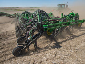
John Deere 1870 Air Hoe Drill
Air Drills
Your Preferred Location
Features
-
Row Spacing: 9-in. (23-cm) paired row 11.8-in. (30-cm) side band
-
Opener: Air Hoe Drill
-
Working Width: 40 ft., 56 ft., 76 ft.
-
Transport Width: 19 ft., 22.6 ft.
-
Fertilizer Placement: In Furrow
Specifications
Dimensions - Nominal mainframe width (between wing-fold pivots): |
5.65 m 18.5 ft |
Dimensions - Number of seed openers: |
40, 56, 76 |
Dimensions - Road clearance with sweep: |
27 cm 10.6 in. |
Dimensions - Spacing and width #1: |
Working width 12.2 m 40 ft Transport height without harrow 3-section model: 5.4 m 17.6 ft Weight With typical options: 9,535 kg 21,020 lb Shank spacing - 30.5 cm 12 in. Row spacing: 30.5-cm side band or 23-cm and 7.6-cm paired row 12-in. side band or 9-in. and 3-in. paired row |
Dimensions - Spacing and width #10: |
|
Dimensions - Spacing and width #11: |
|
Dimensions - Spacing and width #12: |
|
Dimensions - Spacing and width #13: |
|
Dimensions - Spacing and width #14: |
|
Dimensions - Spacing and width #15: |
|
Dimensions - Spacing and width #16: |
|
Dimensions - Spacing and width #17: |
|
Dimensions - Spacing and width #18: |
|
Dimensions - Spacing and width #19: |
|
Dimensions - Spacing and width #2: |
Working width 17.1 m 56 ft Transport height without harrow 4.8 m 15.8 ft Weight 13600 kg 30,000 lb Shank spacing: 30.5 cm 12 in. Row spacing: 30.5-cm side band or 23-cm and 7.6-cm paired row 12-in. side band or 9-in. and 3-in. paired row |
Dimensions - Spacing and width #3: |
Working width 23.2 m 76 ft Transport height without harrow 5.5 m 18 ft Weight With typical options: 26,891 kg 59,285 lb Shank spacing: 30.5 cm 12 in. Row spacing: 30.5-cm side band or 23-cm and 7.6-cm paired row 12-in. side band or 9-in. and 3-in. paired row |
Dimensions - Spacing and width #4: |
|
Dimensions - Spacing and width #5: |
|
Dimensions - Spacing and width #6: |
|
Dimensions - Spacing and width #7: |
|
Dimensions - Spacing and width #8: |
|
Dimensions - Spacing and width #9: |
|
Dimensions - Transport width: |
3-section model: 5.7 m 18.7 ft 5-section model: 5.79, 6.88 m 19, 22.6 ft |
Fertilizer Opener - Type #1: |
Spacing 30.5 cm 12 in. Fertilizer compatibility Anhydrous, liquid, dry Hydraulic precision depth control |
Fertilizer Opener - Type #2: |
|
Fore-Aft Dimensions - Length: |
Lateral frame clearance, opener to opener 91 cm 36 in. Fore-aft frame clearance between ranks 40-ft and 56-ft machines: 127 cm 50 in. 76-ft machine: 142 cm 56 in. |
Freight - F.O.B.: |
Valley City, North Dakota |
Key Specs - Spacing and width #1: |
Shank spacing: 30.5 cm 12 in. Row spacing: 30.5-cm side band or 23-cm and 7.6-cm paired row 12-in. side band or 9-in. and 3-in. paired row |
Key Specs - Spacing and width #2: |
Shank spacing: 30.5 cm 12 in. Row spacing: 30.5-cm side band or 23-cm and 7.6-cm paired row 12-in. side band or 9-in. and 3-in. paired row |
Key Specs - Spacing and width #3: |
Shank spacing: 30.5 cm 12 in. Row spacing: 30.5-cm side band or 23-cm and 7.6-cm paired row 12-in. side band or 9-in. and 3-in. paired row |
Press Wheels - Size: |
40.6 cm 16 in. |
Seed Opener - Penetration force: |
|
Seed Opener - Type #1: |
Spacing 23 and 7.6 cm 9 and 3 in. Trip force 0.04 - 0.53 kN 10 - 120 lbf Paired row |
Seed Opener - Type #2: |
Spacing 30.5 cm 12 in. Trip force 0.04 - 0.53 kN 10 - 120 lbf Side Band |
Seed Opener - Type #3: |
|
Tractor Horsepower Requirements - 41-ft.: |
205 kW 275 hp |
Tractor Horsepower Requirements - 50-ft.: |
56-ft. : 261 kW 350 hp |
Tractor Horsepower Requirements - 61-ft.: |
76-ft. : 340 kW 456 hp |
Tractor Hydraulic Requirements - Minimum SCVs: |
Three for 1870; one for AirPower Cart or two for AirPower 2 Cart, Power Beyond, Case Drain, and hydraulic brakes on applicable carts |
Tractor Hydraulic Requirements - Tractor hydraulic circuit requirements: |
One selective control (SCV) for frame lift; one SCV for wing fold; one selective control valve for setting accumulator pressures on 40 ft and 56 ft |
Tractor Hydraulic Requirements - Tractor hydraulic pressure requirement: |
206.8 bar 3000 psi |
Warning Lights - Standard: |
Yes |
TruSet™ depth and pressure control for 23.2-m (76-ft) 1870
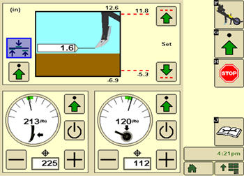 TruSet Screen on GreenStar™ 3 2630 Display
Exclusive TruSet depth and pressure control has taken adjustability on the 23.2-m (76-ft) 1870 to a whole new level. Rather than using manual valve handles, pressure control dials on the monitor let growers make incremental adjustments to trip force and packing pressure conveniently from inside the tractor cab. This also saves time and makes it easier to adapt to changing field conditions.
Controls on the GreenStar 3 2630 Display also allow operators to predetermine a targeted seeding and fertilizer depth. Changes to target maximum and minimum working depth can be made easily on the same run screen. A flick adjustment feature will move openers up or down in short increments if desired. There is no longer a need to get out of the cab to add or remove shims and spacers for depth changes. Plus, TruSet makes side-to-side frame leveling easier. It adjusts at the press of a button on the GreenStar 3 2630 Display.
There is a rotary position sensor under the TruSet plate. In the lower right-hand corner is the valve that regulates the flow of oil to and from the cylinder. There is a sensor associated with each wheel module – or six per machine.
Competitive tractors require an add-on selective control valve (SCV) kit for TruSet to function properly.
RelativeFlow™ Blockage sensing
 RelativeFlow blockage sensing
With the RelativeFlow blockage sensing, operators can see the flow rate of both seed and fertilizer from inside the tractor cab. Sensors on delivery hoses monitor the relative rate of product flow. An easy-to-read display clearly visualizes relative product flow across the drill, from opener to opener. This exclusive technology gives a better view of what is happening across the tool in order to spot problems before blockage occurs.
RelativeFlow Blockage is available on the following models:
- 1890 - 15.2-m (50-ft) and 18.3-m (60-ft)
- 1870 - 12.2-m (40-ft), 17.1-m (56-ft), and 23.2-m (76-ft)
- 1895 - 18.3-m (60-ft)
- N500C – all widths
Below are the GreenStar™ 3 2630 Display screens for the blockage monitoring system. For complete details and information, see the owner’s manual.
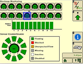 Blockage monitoring screen
The RelativeFlow sensing chart shows the amount of flow through each sensor on the selected tower. Sensitivity for the blockage system can be adjusted if desired, as shown below.
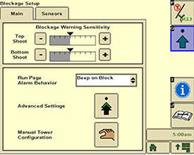 Blockage set-up screen
Blockage warning sensitivity allows the producer to set and change the sensitivity of the sensors to meet their preferences. Increasing the sensitivity means the system is more likely to show a false blockage, while less sensitivity means the system is more likely to miss a blockage.
Multiple run-page alarm behavior options are available for selection.
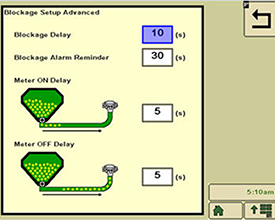 Blockage set-up screen
Below are the Gen 4 display screens for the blockage monitoring system on the N500C.
For complete details and information reference, the owner’s manual.
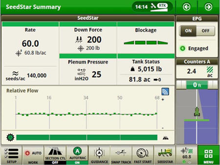 RelativeFlow Blockage configured run page
The SeedStar™ system run page displays the five major run settings. Clicking on any of the tiles will take an operator to that specific page (shown below).
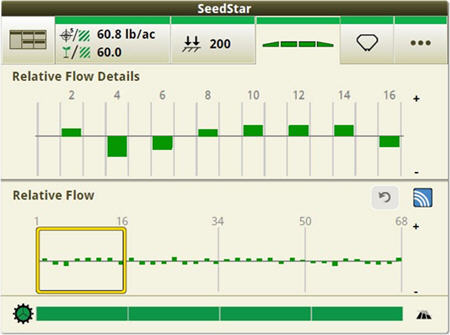 Operators can zoom into flow details by meter section when selecting Blockage tiles
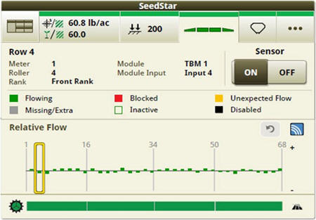 Operators can zoom into the row level to access row/sensor information and turn a sensor on/off independently
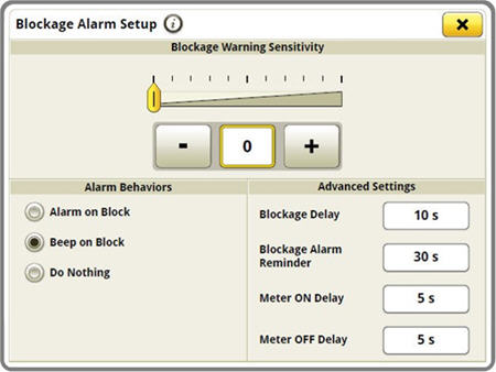 Blockage sensitivities and alarm delays are all set up on one easy-to-navigate screen
Blockage alarm delays can be set up by clicking on the advanced settings button from the blockage set-up screen.
- A blockage delay is how long a blockage should occur before an alarm is sounded.
- The blockage alarm reminder is how often the alarm should sound when a blockage occurs.
- The meter on delay is the time from when the meter is turned on until the blockage sensor should start monitoring for blockage.
- The meter off delay is the time from when the meter is turned off until the blockage sensor should start monitoring to verify no flow.
For more detailed information, see the owner’s manual.
Row spacing options
Paired row vs. side banded
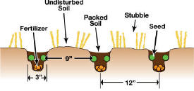 Paired row soil profile
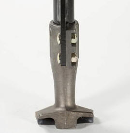
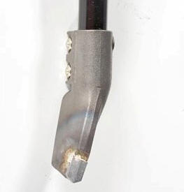
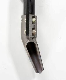
The 1870 has two cast seed boots available. Depending on a grower’s seed and fertilizer placement preference in different soils or different crops, the 1870 can meet the user’s needs. The cast opener was designed with simplicity in mind. One tube is all that is necessary. Switching from single to paired row has never been easier; simply remove the two bolts holding the cast opener in place, remove and replace with new opener.
Paired row
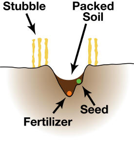
With shanks on 30.5-cm (12-in.) spacing, paired rows can be planted with 22.9-cm (9-in.) spacing. Seed is banded in two rows above and to the sides of the furrow. Total tillage in this zone is 7.6-cm (3-in.) wide with about 25 percent seedbed utilization (SBU).
Seed is laid on a 2-cm (0.75-in.) shelf while fertilizer is placed in a 2.5-cm (1-in.) band between and below the two seed rows.
With paired row placement, the crop is able to access the fertilizer when it needs it. The separation is enough to safely keep the seed from burning. The 1870 provides a well-prepared seedbed for quick emergence and quicker canopy, which will help eliminate weeds. If the operator is looking to swath wider rows, support the heavy green crop.
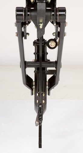
 Paired row opener - rear shot
 Single row/side banded soil profile
Side banded
If the seeding operation calls for side banding, the 1870 is the needed tool. The side-banding seed tube places the seed on a firm bed of soil above and to the side of fertilizer as required. There are 30.5-cm (12-in.) rows across the machine with positive separation between seed and fertilizer up to 11.4 cm (4.5 in.). As the seed germinates and begins to emerge, its roots will be 7.6-cm to 10.2-cm (3-in. to 4-in.) deep and into the nutrient zone.
John Deere recognizes not all seeding conditions are identical and, with the 1870, offers solutions to meet seed and fertilizer placement needs.
 Single row/side banded
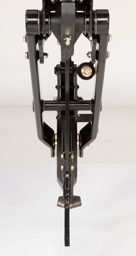
 Single row/side banded - rear shot
 Single row seed boot in-line
 Paired row seed boot in-line
Fertilizer placement
Whether using dry, liquid, or anhydrous ammonia, the John Deere 1870 opener has the options that fit the application needs.
|
|
|
|
|
|
|
AA74478 Aqua anhydrous point |
AA69276 NH3 point |
AA74476 Liquid fertilizer point |
AA69277 Dry fertilizer point |
AA86117 Mud special point |
Description |
Austempered 10B38 boron steel point with hardfaced areas and induction fused carbide inserts to prevent wear. Carbide plates are 4-mm (0.16-in.) thick along the point edge and 6-mm (0.24-in.) thick on the tip. |
||||
Application |
Aqua anhydrous |
Anhydrous |
Liquid fertilizer |
Dry fertilizer** |
Dry fertilizer |
Option code |
1255 |
1250 |
1215/1220 |
--- |
1235 |
Tube diameter (OD) |
9.5 mm (3/8 in.) |
12.7 mm (1/2 in.) |
6.35 mm (1/4 in.) |
--- |
--- |
Pin on |
X |
X |
X |
X |
X |
High top |
X |
X |
X |
X |
X |
Suitable for dry conditions |
X |
X |
X |
X |
X |
Suitable for muddy conditions |
X* |
X* |
X* |
--- |
X |
Dry fertilizer tube add-on |
AA69271 |
AA69271 |
AA69271 |
AA69266 |
--- |
Weight |
0.9 kg (2 lb) |
0.97 kg (2.14 lb) |
0.88 kg (1.95 lb) |
0.86 kg (1.9 lb) |
1.7 kg (3.78 lb) |
Other information |
This form of ammonia is produced by dissolving ammonia gas in water.
AA69272 hose guide is required if dry fertilizer tube is not installed. |
Anhydrous ammonia is compressed into a clear, colorless liquid.
AA69272 hose guide is required if dry fertilizer tube is not installed. |
AA69272 hose guide is required if dry fertilizer tube is not installed. |
--- |
Replaces AA69279.
Wear-resistant hardfaced welds increased by 75 percent.
Thickness increase from 4 to 8 mm (0.16 to 0.3 in.).
Extra 12.7-mm (1/2-in.) weld added close to heavy wear area. |
*If not using dry fertilizer tube add-on **Dry tube required |
|||||


This picture shows the difference between the anhydrous high top and aqua anhydrous tips pictured in the chart above. On the left, the anhydrous high top has a thicker tube wall (1.3-cm [0.5-in.] outer diameter) than the aqua anhydrous tip, though the inner diameter of both tips are equal. The NH3 knives may also be used in combination with the included dry-delivery tube for those wanting to apply NH3 and dry fertilizers simultaneously in the same fertilizer trench.
Additional information for code 1235: the mud-proof combination: dry-fertilizer tube and tip, code 1235, is available for those applying dry fertilizers only. This is recommended for running in sticky, heavy clay-type soils. However, it works well in all soil types to prevent mud from plugging the fertilizer tube opening. This opener is included as base equipment.
If seeding with dry fertilizer only, this option is highly recommended. The fertilizer exits the tube at a lower point, allowing growers desiring to place fertilizer at shallower depths more consistently.
The lower fertilizer exit point also allows the fertilizer to get to the bottom of the trench when more fertilizer and seed separation is desired, and for those light soils that tend to cave in the trench before the fertilizer is placed.
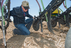
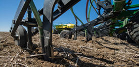 1870 fertilizer shanks engaged in the ground
| Fertilizer tubes | |
| 1.) AA69266 (1250) - Dry fertilizer |  |
| 2.) AA69271 (1220/50/55) - Dry fertilizer with NH3 or liquid |  |
| 3.) AA69272 (1215) - Liquid tube |  |
Agronomic benefits
Implementing moisture conservation farming practices
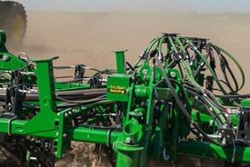
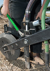
Hydraulic shanks are the workhorses of the 1870 Air Seeding tools. They provide consistent depth control for enhanced seed placement, resulting in more even emergence and more uniform crop maturity at harvest. The hydraulic shank seeding tool uses a rigid frame for strength and support. The openers are designed to allow independent downforce for a more uniform depth across the entire width of the frame.
Seed and fertilizer separation are not compromised when seeding with the 1870. The opener design allows for banding fertilizer to 15.2 cm (6 in.) within the seedbed and up to 11.4 cm (4.5 in.) of separation between the seed and fertilizer. The deep fertilizer opener doubles as a tillage tool to shatter the hard pan for improved root development, water infiltration, and seedbed warmth.

John Deere 1870 key agronomic benefits:
- Freshly exposed black soil is now able to attract the sun’s radiation, warming the ground
- Warmer soil temperature promotes early germination
- Good seed to soil contact
- Necessary for germination to take place
- Seed row has been cleared of any residue or straw
- Provides a clear growth path
- Allows for abundant access to sunlight once the seedling has emerged from the ground.
- Starter nutrients placed next to seed on the shelf, promote early plant growth.
- As the plant strengthens, roots are sent off through mellow dirt into higher rate fertilizer just below the shelf
- The trench left behind helps in cupping rainfall and preventing water run off
- Provides more moisture for the plant during dry years
Depth control
 Seed depth adjustment
When seeding small grains and oil seeds, consistent seed and fertilizer depth control are critical for even emergence. By using two independent hydraulic accumulator force systems, the John Deere opener allows the seed and fertilizer opener trip forces to be set independent of each other.
The use of independent hydraulic accumulator technology, combined with the separate packer wheel force, allows seed-depth gauging to be done on each individual row by the press wheel.
The breakout force for the fertilizer shank is set by adjusting the large accumulator pressure. The press wheel and seed opener down force are set by adjusting pressure on the smaller accumulator. Trip force for the seed opener is set by adjusting a spring shock attached to the seed opener.
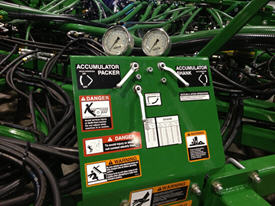 Hydraulic controls to adjust trip force and packing pressure on 12.2-m (40-ft) and 17-m (56-ft) models - the 23.2-m (76-ft) 1870 will have TruSet™ technology for depth control
Seeding with the 1870 gives uncompromised control for seeding operation. Producers are able to maintain safe seed and fertilizer separation with depth placement up to 15.2 cm (6 in.) for the fertilizer.
Setting the fertilizer and seed depth is a very simple process. Fertilizer depth across the machine is set by the frame. Adjusting the seed tube up or down on each individual row-unit sets the preferred seed depth. The tube is positively locked tight by the freshly designed cam system.
Rear cart duals are recommended to help reduce deflection on the front hitch of the tool with a tow-between cart. Adding air pressure, without exceeding maximum psi, will also assist with reducing deflection.
For the 23.2-m (76-ft) 1870 TruSet technology will control depth and pressure. Read more about TruSet here.
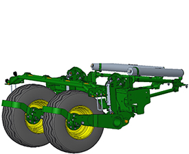
High-flotation kit for 23.2-m (76-ft) 1870 Precision Hoe Drill
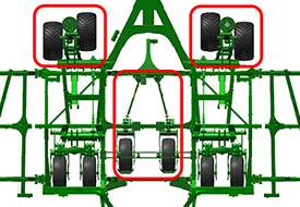
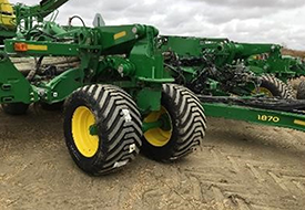
For small-grain producers who want to increase flotation and reduce compaction, a high-flotation kit is available for the 23.2-m (76-ft) 1870 Precision Hoe Drill.
Customer value
The high-flotation kit for the 23.2-m (76-ft) 1870 Precision Hoe Drill provides producers with excellent performance, a boost in uptime, and reduced cost of operation. The high-flotation package consists of two main components: larger front mainframe tires and an in-frame lift assist system. This complete package results in:
- 91.7 percent increase in flat plate area for front wheels
- 60 percent improvement in stuck factor for wheels
- Reduction in tire inflation pressures
- Reduction in ground pressures
- Ability to get in the field sooner if desired
How it works
The high-flotation kit works in two ways:
- The larger front mainframe tires add an increase in flotation to the front of the machine.
- The in-frame lift assist system utilizes the power beyond circuit and a hydraulic valve block to set system pressure, utilizing accumulators to raise and lower the system. The in-frame system has new components to be installed within the existing mainframe to increase flotation and allow the machine weight to be spread across additional tire surface area.
High-flotation kit components
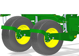
Larger front mainframe tires:
The mainframe and wing wheel scrapers have been redesigned to better meet producer needs. These scrapers are included in the high-flotation kit. BA33708 can also be ordered separately if the grower does not want the flotation kit.
| Attachment | Description |
| BA33708 | Main frame and wing wheel scrapers NOTE: Order one kit per 23.2-m (76-ft) 1870 Drill. |
This kit does not include any 440/55R18 tires for the lift assist system. The producer will use the 440/55R18 tires from the mainframe front that will be replaced by 550/45-22.5 tires as part of the kit pre-delivery inspection (PDI) process.
Compatibility
This kit is compatible with all 23.2-m (76-ft) 1870 Precision Hoe Drills.
Ordering
This kit will be initially offered as a product enhancement program (PEP). See PEP #18AX461 for more details.
| Attachment | Description |
| MPA10950 | 23.2-m (76-ft) 1870 High-flotation PEP kit NOTE: Includes larger front tires and assembly and lift assist system. Does not include 440/55R18 tires. |
Mainframe and wing wheel scrapers
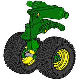 Front mainframe tires
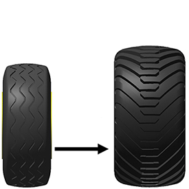 91.7 percent increase in flat plate area
| Standard front tires | High-flotation front tires | |
| Tire | 440/55R18 | 550/45-22.5 |
| Load capacity | 4377.2 kg (9650 lb) | 3646.9 kg (8040 lb) |
| Inflation pressure | 5 bar (73 psi) | 1.5 bar (22 psi) |
| Outside diameter | 94.2 cm (37.1 in.) | 106.9 cm (42.1 in.) |
| Width | 43.4 cm (17.1 in.) | 55.1 cm (21.7 in.) |
| Static loaded radius | 42.2 cm (16.6 in.) | 47 cm (18.5 in.) |
| Flat plate area | 1006.5 cm2 (156 sq in.) | 1929 cm2 (299 sq in.) |
Lift assist system: