

John Deere 913 V-Ripper

Description
- Adjustable standard spacing prevents side movement
- V-pattern frame promotes leading-edge shattering
- LaserRip™ Extreme points
- Heavy-duty steel ripper points
Models
Strong V-pattern frame promotes leading-edge shattering of center shank and material flow
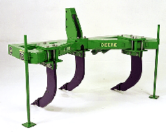 913 V-Ripper
The frame design of the 913 V-Ripper positions the standards in a V pattern:
- Promotes leading-edge shattering of the center shank and material flow through the machine
The 127-mm x 178-mm (5-in. x 7-in.) cross-section frame has 10-mm (3/8-in.) thick walls:
- Provides strength to handle tractors of up to 150 power take-off (PTO) horsepower
- Same frame-size tubing as non-expandable 915 V-Ripper
- Parking stands are included in base equipment
Two-position integral hitch to meet operator requirements
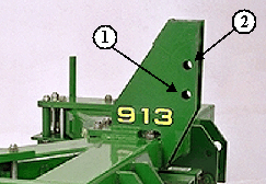 Low and high positions on 3-point mast
3-point hitch hookup is for Category 2 or 3N tractors.
The integral hitch can be set to two positions:
- 1 = Low position
Gives maximum transport clearance and allows ripping to approximately 508 mm (20 in.) deep with the 838-mm (33-in.) standards. - 2 = High position
Enables ripping to a maximum depth of 584 mm (23 in.) deep with the 838-mm (33-in.) standards.
Soil probe helps to determine proper operating depth
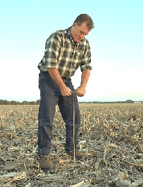 Soil probe
The soil probe helps operators to determine the proper operating depth of their ripper points,
38 mm (1.5 in.) below the bottom of the compaction layer.
The probe allows obtaining the maximum amount of soil fracturing from the entire family of John Deere ripper points. Marked in 51-mm (2-in.) increments from 254 mm to 559 mm (10 in. to 22 in.), the probe provides accurate feedback of compaction layer depth.
It is stored on the mainframe of the ripper for convenient access. The operator's manual explains the proper use of the soil probe.
Specifications
- Depth control - Option 1: Intergral units are controlled by tractor, rockshaft, and gauge wheels
- Hitch - Options: Integral
- Hitch - Three-point hitch requirements: Category 2 or 3N with Quik Coupler<br/>Category 3N without Quik Coupler
- Key Specs - Operating depth: Maximum<br/>58.4 cm<br/>23 in.<br/>
- Key Specs - Spacings: 50.8 cm<br/>20 in.<br/>63.5 cm<br/>25 in.<br/>76.2 cm<br/>30 in.
- Key Specs - Transport width: Option 1: 2.1 m<br/>7 ft<br/>Option 2: 2.1 m<br/>Option 3: 2.1 m
- Key Specs - Working width: Option 1: 2.5 m<br/>8.33 ft<br/>Option 2: 3.2 m<br/>10.42 ft<br/>Option 3: 3.8 m<br/>12.5 ft
- Operating depth - Maximum: 58.4 cm<br/>23 in.
- Standard options - Option 1: Trip force<br/>5,443 kg<br/>12,000 lb<br/>Standard type<br/>Straight or parabolic with wear shin<br/>Shear-bolt
- Standard options - Option 2: Trip force<br/>2,540 kg<br/>5,600 lb<br/>Standard type<br/>Straight with wear shin or parabolic<br/>Safety-trip
- Standard options - Option 3: Trip force<br/>2,404 kg<br/>5,300 lb<br/>Standard type<br/>Straight with wear shin or parabolic<br/>Cushion-trip
- Standard options - Option 4: Trip force<br/>1,451.5 to 2,404 kg<br/>3,200 to 5,300 lb<br/>Standard type<br/>Parabolic<br/>Spring-reset rock standard
- Standard options - Spacings: 50.8 cm<br/>20 in.<br/>63.5 cm<br/>25 in.<br/>76.2 cm<br/>30 in.
- Tool configuration - Option 1: Standard: 3, spacing: 50.8 cm<br/>20 in.
- Tool configuration - Option 2: Standard: 3, spacing: 63.5 cm<br/>25 in.
- Tool configuration - Option 3: Standard: 3, spacing: 76.2 cm<br/>30 in.
- Tool configuration - Type: V-ripper
- Transport width - Option 1: 2.1 m<br/>7 ft
- Transport width - Option 2: 2.1 m<br/>7 ft
- Transport width - Option 3: 2.1 m<br/>7 ft
- Working width - Option 1: 2.5 m<br/>8.33 ft
- Working width - Option 2: 3.2 m<br/>10.42 ft
- Working width - Option 3: 3.8 m<br/>12.5 ft
Copy Set
Strong V-pattern frame promotes leading-edge shattering of center shank and material flow
913 V-Ripper
The frame design of the 913 V-Ripper positions the standards in a V pattern:
- Promotes leading-edge shattering of the center shank and material flow through the machine
The 127-mm x 178-mm (5-in. x 7-in.) cross-section frame has 10-mm (3/8-in.) thick walls:
- Provides strength to handle tractors of up to 150 power take-off (PTO) horsepower
- Same frame-size tubing as non-expandable 915 V-Ripper
- Parking stands are included in base equipment
Two-position integral hitch to meet operator requirements
Low and high positions on 3-point mast
3-point hitch hookup is for Category 2 or 3N tractors.
The integral hitch can be set to two positions:
- 1 = Low position
Gives maximum transport clearance and allows ripping to approximately 508 mm (20 in.) deep with the 838-mm (33-in.) standards. - 2 = High position
Enables ripping to a maximum depth of 584 mm (23 in.) deep with the 838-mm (33-in.) standards.
Soil probe helps to determine proper operating depth
Soil probe
The soil probe helps operators to determine the proper operating depth of their ripper points,
38 mm (1.5 in.) below the bottom of the compaction layer.
The probe allows obtaining the maximum amount of soil fracturing from the entire family of John Deere ripper points. Marked in 51-mm (2-in.) increments from 254 mm to 559 mm (10 in. to 22 in.), the probe provides accurate feedback of compaction layer depth.
It is stored on the mainframe of the ripper for convenient access. The operator's manual explains the proper use of the soil probe.